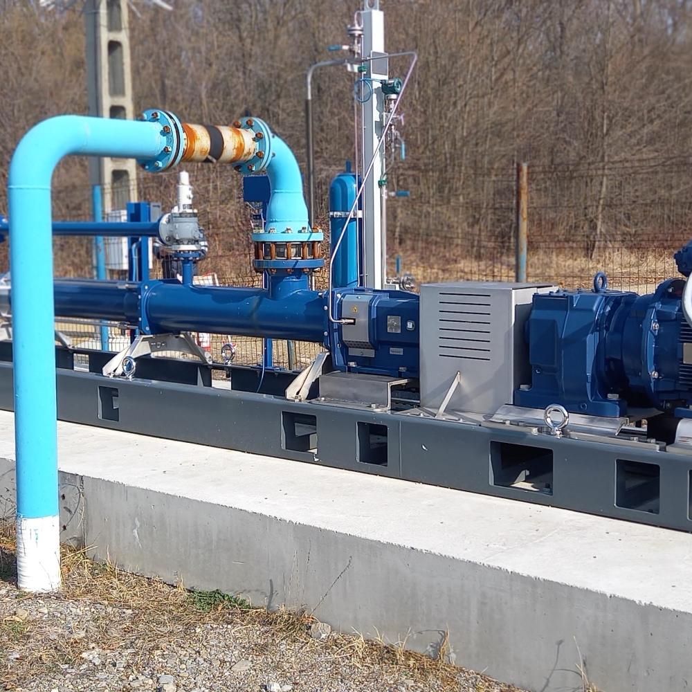
PCP Installed in Multiphase Boosting Application
PCM provided a customer with a 120A24-HR pump, compliant with API 676, for use in a multiphase boosting application.
The customer had a pad of oil wells that was located a significant distance from the processing facility. This resulted in a high back pressure in the flow line. These wells produce gas up the casing, which needs to be recombined with the liquids produced up the tubing to be sent to the processing facility. The high pressure in the flowline therefore limited the drawdown that was possible in the wells, and so production from the wells was reduced. By installing a progressing cavity pump equipped with PCM Slugger technology at the well pad, the customer has been able to reduce the back pressure on the wells from 15-20 bar down to 1 bar.
This has both reduced stress on the downhole pumps in the wells and increased production by 7%.
PCM’s solution Slugger technology
PCM’s solution for the customer was a single progressing cavity pump, which can handle heavy oil and gas, even if solids and water are also present. The PCM Slugger technology was chosen due the possibility of a high gas fraction at the pump intake when the upstream pressure was reduced. While PCPs can pump gas, the run life may be reduced due to a non-linear pressure gradient inside the pump. The hydraulic regulators inherent in the PCM Slugger technology linearize the pressure gradient, allowing good run-life at up to 90% gas volume fraction at the pump intake.
A PCP is a positive displacement pump, which means that the flow rate is proportional to the pump speed. However, in this case, the flow rate coming into the pump would be variable as some of the wells on the pad go offline or come back online, or as the individual wells’ productivity changes. Therefore, PCM designed a customized control system using a variable speed drive (VSD) to change the pump speed according to the available flow rate from the wells at any given time.
To ensure that no leakage of oil to the environment would be possible, an API Plan 53B seal system was included with the pump. Despite the presence of a lubricating barrier fluid, there was a concern that the high gas fraction at the pump intake may have a negative effect on the shaft seals. Therefore, the pump was configured with the shaft at the discharge end of the pump. The seals operate at the discharge pressure, but the gas volume fraction is much smaller due to the higher pressure.
A pressure relief valve was included to redirect flow from the pump discharge to the intake in the event of a blockage in the flowline. A bypass line was also included so that the wells could still operate when the pump is shut off, either for maintenance, or because it is not needed.
Discover